
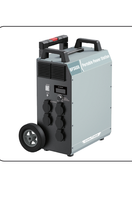
A supplier-side matching method for distributors, solar installers and project buyers: how to read the published DC input window, why open-circuit voltage at low ambient temperature is the buyer check, how the 25A current ceiling bounds series and parallel layout, and how the wattage ceiling and built-in MPPT rating set fill time for the BP3600 and BP2400.
Panel matching for a solar panel portable power station reduces to three published limits: the DC voltage window, the 25A current ceiling and the wattage ceiling. Read together, these three decide how much array the input will accept and how long a full charge takes. Everything below is a way to read those published figures and set an array against them, not a scene-by-scene buying recommendation.
The three limits in one place
The input accepts a voltage range, caps current at 25A MAX, and caps total solar power at a published wattage. A panel array has to satisfy all three at the same time; meeting two of them does not make a usable match.
How to read a panel voltage window against a published machine input range
The DC input is published as a range, not a single figure. On the BP3600 the solar input is 12-150VDC; on the BP2400 it is 12-105VDC. Both carry the same 25A MAX current ceiling. Those ranges are the working envelope of the built-in MPPT controller, and an array has to produce an operating voltage that sits inside the envelope during the hours the system is actually charging.
A panel does not report one fixed voltage. Its datasheet gives an open-circuit figure and a maximum-power-point figure, and the MPPT controller works the array at the maximum-power point while the array is loaded. That loaded voltage is the one that matters for normal operation, and it has to be comfortably inside the window rather than parked at either boundary. A maximum-power voltage close to the upper limit leaves no room for the array to drift upward as temperature falls, and a maximum-power voltage close to the lower limit risks dropping out of the working range before the controller can start. Matching on the middle of the band is the practical way to leave margin on both ends.
Panel strings are usually described by their maximum-power voltage and current, and buyers tend to check only those. The open-circuit figure is what the input sees before the controller begins drawing current, so it deserves the same attention as the loaded value. When a string sits near the top of the window, the open-circuit figure is the number that decides whether the input stays within its published range.
Why open-circuit voltage at low ambient temperature is the buyer check that protects the input
Open-circuit voltage rises as cell temperature falls, so the coldest condition the array will see is the condition that stresses the input window hardest. Most panel datasheets carry a temperature coefficient for open-circuit voltage. That coefficient is panel-specific and it is the buyer's job to apply it, because the published machine window is a fixed figure and the panel's cold-weather voltage is not.
The check is straightforward. Take the string's open-circuit voltage at standard test conditions, apply the panel's own voltage coefficient to the lowest expected ambient or cell temperature at the installation site, and compare the result with the upper end of the machine window — 150VDC on the BP3600, 105VDC on the BP2400. A string that fits at moderate temperature can exceed the ceiling on a cold morning if the margin is thin. The calculation uses figures the panel supplier publishes; the machine window is the fixed side of the comparison.
Two practical consequences follow. Longer series strings are the arrangement most exposed to this effect, because the cold-weather rise of each panel adds together. And a string that has been sized by maximum-power voltage alone has not been checked at all. If the panel coefficient is not on hand, obtain it from the panel supplier before fixing the string length.
How the 25A current ceiling constrains series and parallel arrangement
The current ceiling acts on the array current the input receives, not on the nameplate current of a single panel. In a series string the current stays at the level of one panel while the voltages add; in a parallel arrangement the currents add while the voltage stays at one panel's level. This is the lever that reconciles a large array with a fixed window.
For a given total array power, series connection raises voltage toward the upper limit and keeps current low, while parallel connection keeps voltage low and pushes current toward 25A. Because the input stops accepting current beyond 25A, an array wired in parallel that exceeds the ceiling will not deliver the surplus; the extra panel current is clipped. Series strings are therefore the usual way to use a wide voltage window, provided the cold-weather open-circuit check above is satisfied. Parallel strings suit lower total power or a string voltage that must stay near the bottom of the window.
Hybrid arrangements, meaning parallel strings of series panels, are common on larger arrays, and they need the same two checks applied to the combined result: total open-circuit voltage at the cold condition against the upper limit, and total array current against 25A. Both figures describe the array as wired, not the individual panels.
A portable power station with solar panel input rated at 25A MAX will run into this ceiling before it runs into the wattage ceiling in some configurations, and the reverse in others. Whichever limit binds first is the one that sets the usable array, which is why the two ceilings are treated together rather than separately.
How the wattage ceiling and the built-in MPPT rating set the fill time
The wattage ceiling and the controller rating are published as a pair with a full-charge time, and that pair is the clearest statement of what the input can actually absorb. The BP3600 carries a built-in 2400W MPPT controller, a solar charging maximum of 2400W, and a full charge in 1.5h. The BP2400 carries a built-in 1200W MPPT controller, a solar charging maximum of 1200W, and a full charge in 2.5h. The controller rating and the solar maximum are the same figure in each case, which means the ceiling is set by the controller itself.
Fill time is bounded from the array side as well. An array whose total nameplate wattage sits below the ceiling cannot drive the input to its rated absorption, so the published full-charge time is an upper bound on array performance and not a guarantee. An array above the ceiling is clipped at the controller rating; the surplus nameplate wattage adds cost and mounting load without shortening the charge. Sizing the array at or just under the published ceiling is the arrangement that uses the input fully without paying for capacity the controller will not pass.
Because the input is a DC solar input with a published wattage ceiling, all three limits interact in one direction: a larger array only shortens fill time while voltage stays inside the window and current stays under 25A. Once any one of the three is exceeded on the array side, additional panels stop improving charge time.
Buyer checklist before ordering panels
- Window fit. Confirm the array's operating voltage falls inside 12-150VDC for the BP3600 or 12-105VDC for the BP2400, with margin at both ends rather than at either edge.
- Total nameplate wattage against the ceiling. Add the panel ratings as wired and compare with 2400W for the BP3600 or 1200W for the BP2400. Decide deliberately whether you are sizing under the ceiling for a realistic fill time or at it for maximum absorption.
- Array current against 25A. Calculate the current the wired array presents to the input, not the current of a single panel, and keep it at or under 25A MAX.
- Connector and cable suitability. Confirm the panel connectors mate with the machine input and that cable current rating and voltage rating suit the array as configured. The input figures define what the machine accepts; the cable and connector have to carry it.
- Charging temperature window. The published charging temperature is 0C to 45C. Site conditions outside that band fall outside the published charging range, so plan the charge window around it.
- Cold-condition open-circuit check. Apply the panel's own voltage coefficient to the lowest expected temperature and re-confirm the upper limit before fixing string length.
Additional published figures for the BP3600 that bear on installation and handling: 3430Wh LiFePO4 battery, discharging temperature minus 20C to 50C, unit IP53, battery pack IP66, 5-year warranty, CE, RoHS and UN 38.3. The BP2400 is published with a 2662Wh LiFePO4 battery, 0C to 45C charging temperature, 5-year warranty, CE, RoHS and UN 38.3. The DP3600iL is published with a built-in 1200W MPPT controller and a 2662Wh battery, at 3600VA rated and 7200VA peak.
Published solar input specifications side by side
| Parameter | BP3600 | BP2400 |
|---|---|---|
| Solar input voltage | 12-150VDC | 12-105VDC |
| Current ceiling | 25A MAX | 25A MAX |
| Built-in MPPT controller | 2400W | 1200W |
| Solar charging maximum | 2400W | 1200W |
| Full charge time | 1.5h | 2.5h |
| Battery | 3430Wh LiFePO4 | 2662Wh LiFePO4 |
| Charging temperature | 0C to 45C | 0C to 45C |
| Warranty | 5-year | 5-year |
| Compliance | CE, RoHS, UN 38.3 | CE, RoHS, UN 38.3 |
FAQ
Does a larger panel array than the published ceiling shorten fill time?
No. The controller rating and the solar charging maximum are the same published figure on each model, 2400W on the BP3600 and 1200W on the BP2400, so nameplate wattage above that ceiling is not absorbed by the input. A larger array adds cost and mounting load without moving the charge time, and it may also raise array current toward the 25A ceiling, which is a separate constraint that clipping does not remove.
Can mixed panel models be combined on one input?
Panels in the same series string are expected to carry the same current, and panels in parallel are expected to share the same voltage, so pairing mismatched models leaves the weaker unit limiting the shared path. If mixed models must be used, treat each string as its own electrical unit and check the combined wired result against the voltage window, the 25A ceiling and the wattage ceiling. The published input figures apply to the array as wired, not to each model individually.
What should be sent to the supplier when requesting a matched panel configuration?
Send the model of the power station, the panel datasheet including maximum-power voltage and current, open-circuit voltage and its temperature coefficient, the planned series and parallel layout, and the lowest expected ambient temperature at the site. With those figures the array can be checked against the published window, the 25A ceiling and the wattage ceiling, and the expected fill time can be related to the published full-charge pair. Without the cold-temperature coefficient, the upper-limit check cannot be completed.
Is the voltage window the same thing as the MPPT input range?
The published DC input range is the working envelope within which the built-in MPPT controller operates the array. Treat the two ends of that range as hard boundaries for the wired array, including the cold-condition open-circuit value, rather than as figures to approach during normal operation.
For confirmation before fixing an array, check the published solar input window and MPPT rating on the product page of the model you are specifying, and match panels to those published numbers rather than to a target fill time on its own.